Optics
Unveiling Hidden Beauty: Dielectric Coatings and Angle Dependence in Kinetic Art
The core of my artwork lies in repurposing scrap optics from the laser industry. These components are coated with durable and spectrally selective dielectric layers.
Deemed unusable for their original precision applications, these coated optics exhibit a strong angular sensitivity to light which make them perfect for mobiles. I leverage this sensitivity – rooted in the principles of thin-film interference – as their relentless pirouetting reveals new hues with each gust of wind.
It is as if the mobile is painting with light, with each movement generating a new and beautiful color display, highlighting the elegance of both the motion and the spectral shifts from the dichroic coatings.
Coatings
Coatings are the key. Lasers function by amplifying feedback (reflections) of a very specific color at greater than 99%. Mirrors with this high degree of reflectivity are quite specialized and require careful engineering to be functional.

The stacks of layers that are built up to establish such a reflection have a well-designed thickness and specific angle of incidence. Inflection Point Mobiles uses the spectrally selective nature of these layered, dielectric coatings and then varies the angle of incidence by allowing the glass to drift with the wind. As the angle varies, the effective thickness of the layers will shift.
This results in a perceived color change – both in transmission and reflection.
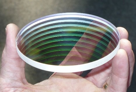
I collected any scrap coated glass, knowing that these specialized optics would be fabulous – once incorporated in mobiles. Here is a picture of a single optic with a graphic affixed to one surface of the dichroic. You can see the transmitted light on the left is magenta and the reflection is green.
IPM Glass
Other industries utilize these multi-layered coatings – also known as “interference filters” – most notably in the biomedical field. Thin biopsy specimen slides were initially illuminated with filtered light to enhance contrast of a stained sample. The industry has gone from using simple colored glass to enhance this task to highly sophisticated optical systems using computerized evaluation of the results. The coatings made with this technology are sometimes known as ‘dichroics’ because they have the ability to separate light. Once again, these filters are very sensitive to any angular change – an artifact that is accentuated when used in a mobile. This optical filter industry is another fabulous trove for artists as their mirrors are often quite spectacular.
Inventory
Dichroic mirrors offer a unique visual experience due to their ability to reflect and transmit different wavelengths of light based on the angle of incidence. This property, known as angular dependence, makes them perfectly suited for kinetic art. As a mobile moves, the changing angles of the dichroic mirrors will create dynamic and ever-shifting displays of color and light, creating a truly captivating visual experience.
The use of dichroic mirrors in mobiles is a niche area within the broader kinetic art form. While many talented artisans create mobiles, few incorporate dichroic mirrors. Perhaps unfamiliarity with the material may have limited artists from experimenting with dichroics. The most pressing rationale is based on their high cost. Even salvaged optics are prohibitively expensive. A single scrap dichroic optic and run ~$50. At this rate, a mobile with 10 dichroics in it would carry a staggering price tag. Currently available pieces employing coated optics are often static displays of identical optics – geometrically arranged. These works seem to underutilize the full angular sensitivity of the coating.
I have evolved techniques and designs that emphasize both fluidic motion and the optical effects of the mirrors. This approach enhances spectral shifts, highlighting the chromatic effect of dielectrics in kinetic art. At IPM I have engaged industry contacts to source an ample supply of mobile-ready optics which are incorporated into my designs at affordable prices. My inventory is well stocked with large plates that can be converted to any diameter necessary to complete a desired design
Design Evolution & Lessons Learned
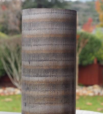
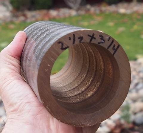
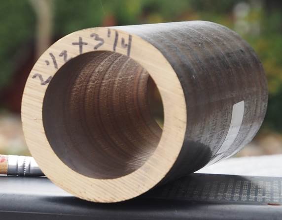
Back in 1983 I initially tried epoxying small glass mirrors onto the ends of brass rod stock. While I was able to balance my design, the fragility of the metal-glass joint made it highly impractical. A ruggedized assembly was needed. The optic needed an enclosure to shield it. I also needed a way to attach the protective ring to the rod arm. After some experimentation, 932 bronze was chosen as the ring material. This ring enclosure can be drilled. tapped and threaded in standard fashion, making maintenance and changes quite easy. 932 bronze is easily machined and impervious to salt water. With this corrosion resistant trait, it has become the standard material for shaft bushings in naval vessels and then all sorts of industrial machinery – making the selection of available surplus 932 tubing quite plentiful. Used and scrap bronze tubes can be found for bargain prices. Aluminum is a viable option, but this metal is not utilized as much as bronze for shaft bearings and thus the selection of available hollow sizes is limited. Stainless too has been used for rings on occasion, but its durability and luster come at a price, plus the increased difficulty in machining restrict its usage in for rings in my designs.
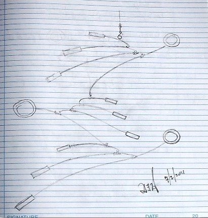
Traditionally, I would sketch a concept in a notebook and then take that to the machine shop. Over time I found that incorporating this initial sketch into CAD allows me to spin the model in 3D – something I could not really do with a two dimensional drawing. While tedious, this extra step has proven to be very beneficial. I do not attempt balance dynamics or seek moment-of-inertia information from the exercise – just a visual confirmation of clearances and aesthetics.
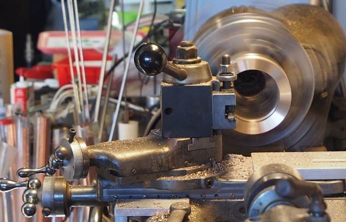
The Ring
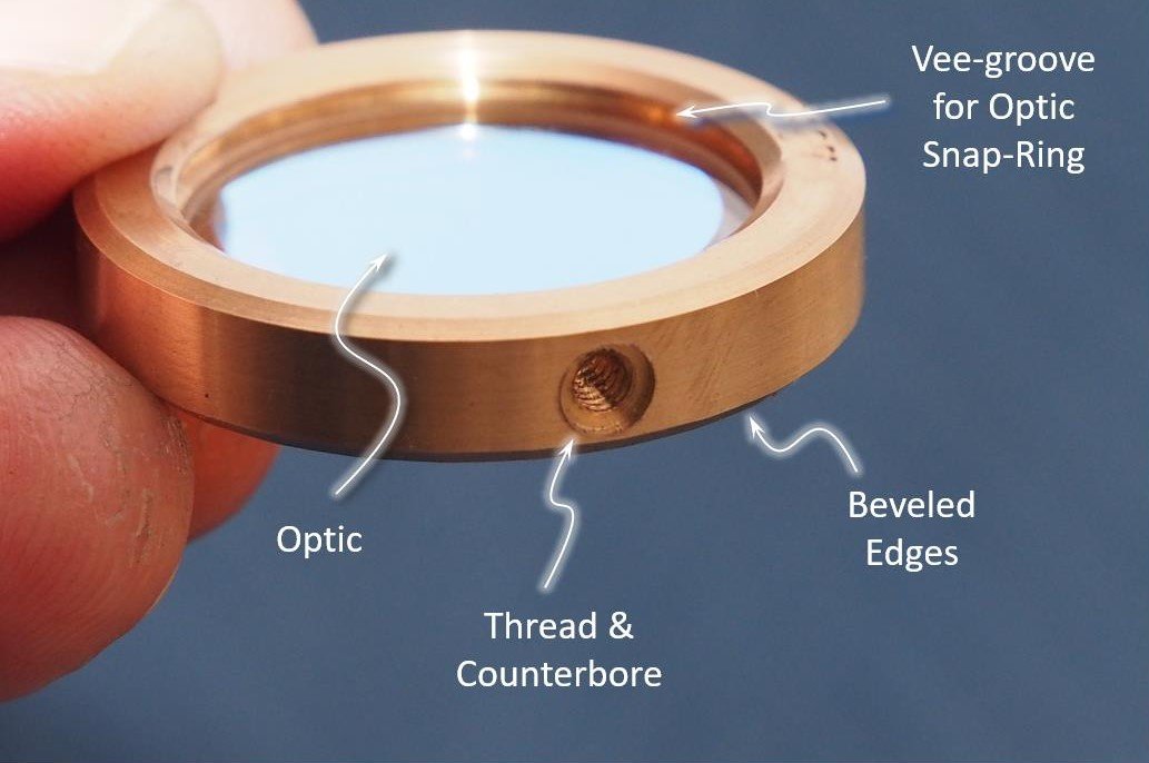
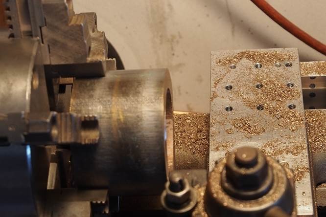
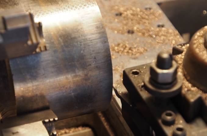
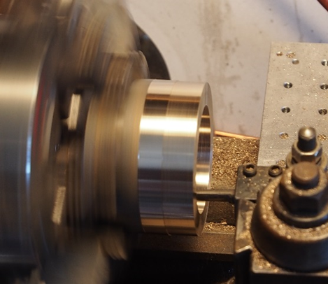
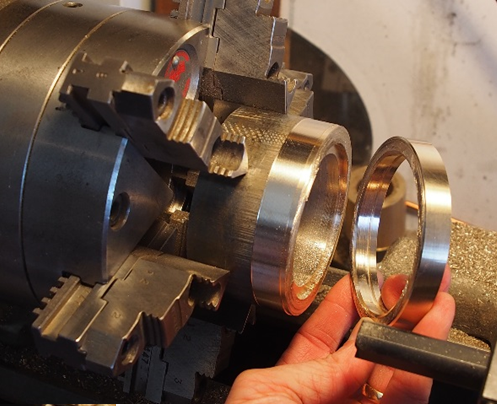
Once an optic is selected for use, a slightly larger piece of bronze is chosen to encircle and protect the glass. Its outer diameter is cleaned up and an inner through-hole is drilled. A small, precision counter bore is machined to nestle the OD of the mirror.
The depth of this CB is dictated by the thickness of the optic. A snap-ring made from spring-temper phosphor bronze is used to secure the reflector in place. The snap ring is captured in the ring by a small internal vee-groove machined at the top of the optic counter-bore.
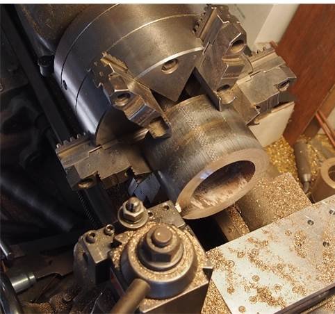
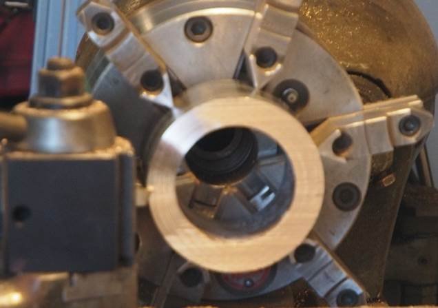
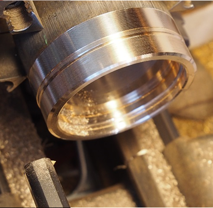
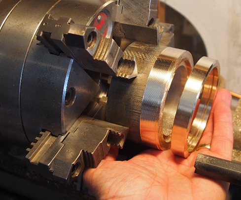
These ring fabricating steps are typically done with small-volume production steps as rings of the same size are often needed for the inventory of available glass. The rings then receive small bevels on the ID and OD on both sides of the ring to make it stylish and attractive.
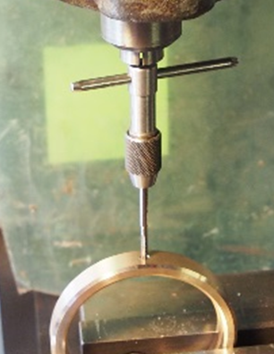
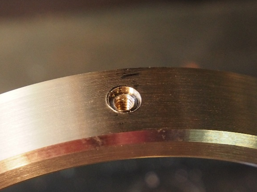
The final step for a bronze ring is to cross-drill, tap and counter-bore the attachment point. The bronze ring is secured to the tier branch arm with the appropriate size set-screw. The stainless screw is threaded in to the arm (with some Loctite). The ring is then secured to this screw and the arm buries its end into the CB that was part of the cross-drilling operation. This method makes for a robust and clean-looking approach regardless of the arm diameter.
Ring Machining Sequence
*Click to see details


Fulcrum Springs
Addressing the adjustable fulcrum, I settled on a torsional spring design that securely clamps the arm – but can be shifted along the arm, by “opening up” the spring and sliding it to the desired spot. This key part, precision sized to the branch arm diameter, is known as a ‘Fulcrum Spring’ or FS. To alter the balance point, you unwind the spring, set it to the new fulcrum point and release. When sized correctly, it works admirably
Center-of-Gravity
In my designs, the fulcrum spring, branch arm and hook-loop are all hopelessly intertwined. It is difficult to describe the function of one without discussing the others.
Key to the arm is its Center-of-gravity, Cg or balance point, around which most attachments are made. A simple loop, bent into the rod is what Calder and most makers do at this location on the arm.
Admittedly, some weld an attachment loop for the next section of the tier, but the net effect is identical: a fulcrum position has been defined by the loop. When using this loop, if the angle of the arm is incorrect, it can be adjusted by adding or subtracting mass at the blade end. It would make sense for Calder to loop a large rod, attach a slightly-too-large blade mass to it, witness its angle of balance and then grind off metal until the proper repose was attained. Or punch a hole in the blade.
I wanted an adjustable fulcrum to be able to dial-in the specific tier arrangement desired. Once while working on a large, completed piece, one of the key optics was damaged. Replacement was a different piece of glass with a new ring – and a new mass – throwing the tier design into jeopardy. An adaptable approach was needed where balance compensation was done by shifting the fulcrum without altering the mass of the ring or the optic.
Using the flexibility of the Fulcrum Spring, I can arrange the tiers to suit almost any desirable design
Fabrication
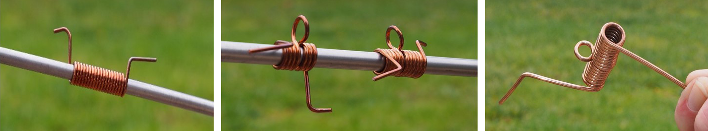
I wrap hard-temper 510 phosphor-bronze wire onto a precision mandrel that is clamped in the chuck. This is done on a rigid lathe as the materials and gauges are hard to bend with just hand tools. I spin the lathe manually, feeding the wire in to form the helix. I pause after a few wraps and guide the wire out of the spring axis – to form a loop – and then re-engage the original-wrap center-line to finish the part.
It’s a spring with an off-axis loop in the middle and flying leads for adjustment. Once the arm/optic are properly balanced, the flying leads are clipped off, leaving a visually aesthetic branch arm. This has proven to be a successful manufacturing method.
Arms
One of the main elements in the construction of a mobile ‘tier’ is the branch arm. This arm can be made from a variety of materials that lend themselves to easy-machining, such as copper, brass, bronze, stainless, even bamboo or teak. IPM designs predominantly use hollow stainless-steel tubing – tending to prefer hard-drawn temper. This type of steel will take an intentional “set” and there-after resist bending. It needs to be proportionally sized in both OD and length for the mated optic ring OD.
Hooks and Loops
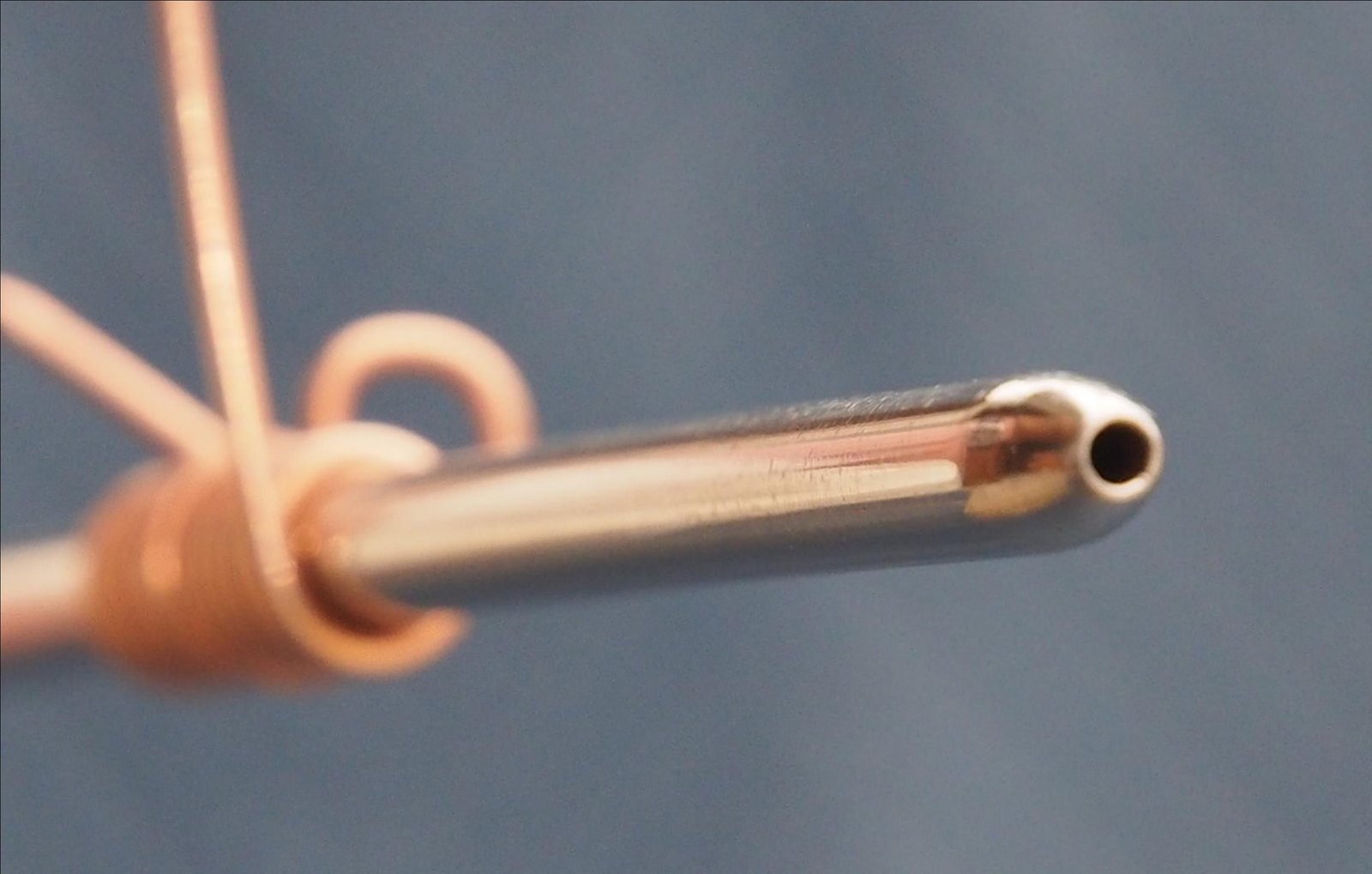
The arm is a hollow tube that is threaded at the ring interface and bullet-nosed at the other end. The ID of the branch arm is closely matched to the wire OD. The hook itself is made from hard-temper Phosphor Bronze wire that extends as much of the full length of the tube as possible.
Usually, the branch arm has a slight curvature to it, and this in turn helps lock the hook wire inside the arm. I try to make it difficult “push-fit”. This wire is embedded in the tube and is held by friction with occasional assistance from a thread-locker. When excessively loose engagements are encountered, I generally kink the wire at several points and crimp the arm to ensure proper securing of the hook. The mass the hook is intended to support is usually measured if fractions of ounces. On occasion, larger tiers have exceeded several pounds with the friction method surviving outdoor demonstrations. For permanence, as well as safety, an induction weld can be used to secure the hooks if needed.
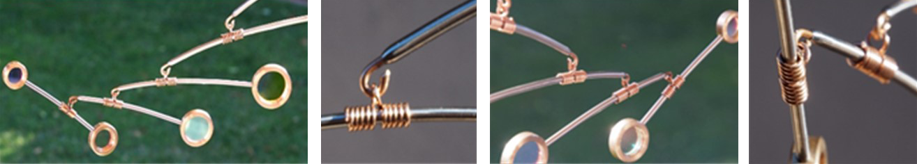
To optimize the stability and movement of each tier’s branch arms, a precise hook and loop engagement is essential. The goal is to achieve an optimal connection that permits limited, controlled movement that encourages harmonious collaboration among the arms. This approach enhances the overall aesthetic appeal of the tier by facilitating a synchronized and elegant interplay.
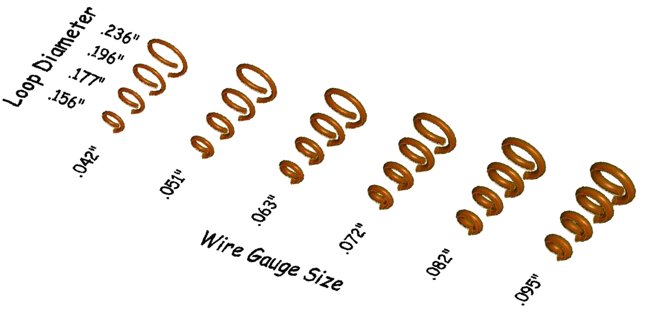
A linkage that is too loose will result in excessive swaying, while a connection that is too tight will constrictively restrict motion. The matrix above is quite subtle in appearance, but functionally these parameters are significant and have a profound impact on how the tier behaves when it’s in motion.
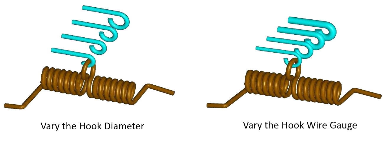
The renditions below show how hook diameter and wire gauge size can affect dynamics.
Angle of Incidence
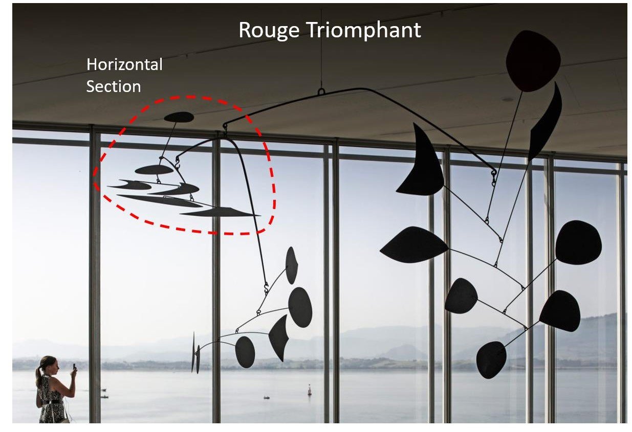
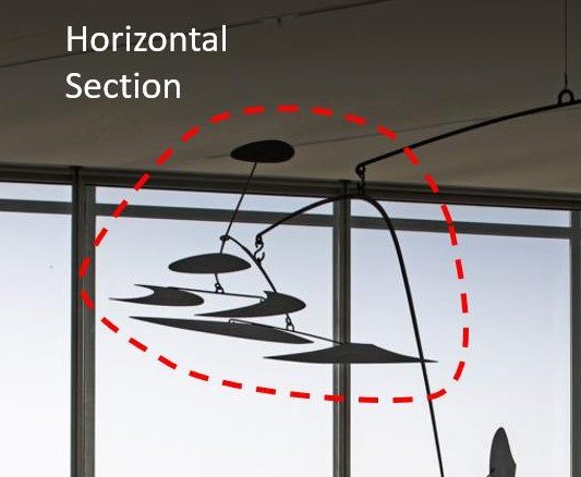
The blades in the Vertical Foliage mobile by Calder (above) are all arranged “vertically”. You can see the distinction from his Rouge Triomphant “horizontal” section. He often made horizontal shapes appear aeronautical, teasing the similarity with bird-like shapes. They absolutely transport you when viewed up-close.
Those that have placed mobiles in their homes will recognize that the horizontal oriented sections will collect dust. By contrast, vertical tiers fare much better – not having the same accumulation footprint. Those mounted flat will, over time, capture residues, cob webs and home debris. If mounted outdoors, they will be subject to rain-water, dust, dirt, bird-droppings, very similar to a car windshield left unattended. Either way, these distinctions are quite critical for mobiles with reflective optics. All of these environmental hazards led me to design the replaceable optic method – using the snap-ring. Everything can be disassembled, cleaned and quickly put back on display.
Optics mounted vertically will reflect sun-light in the early morning and at dusk – under low angles of incidence. During the peak of the day, the sun is high overhead and has such a steep angle to the glass – that it provides no substantial reflection.
By contrast, optics mounted horizontally function best during midday when the sun has an unimpeded line of sight to the glass at noon.
So, the trade-off is: mount the optics vertically for the optimal morning/evening reflections and have less maintenance – or – mount the optics horizontally to get the best reflections during the peak of the afternoon, with the proviso that maintenance on a regular basis is required.
Arrangements – Articulators and Alternators
When branch arms, optics, springs are all determined and fabricated, then it’s time to assemble. Simple constructions of a few arm/ring combinations is known as a tier. These tiers can then be used as sub-assemblies in a larger composition.
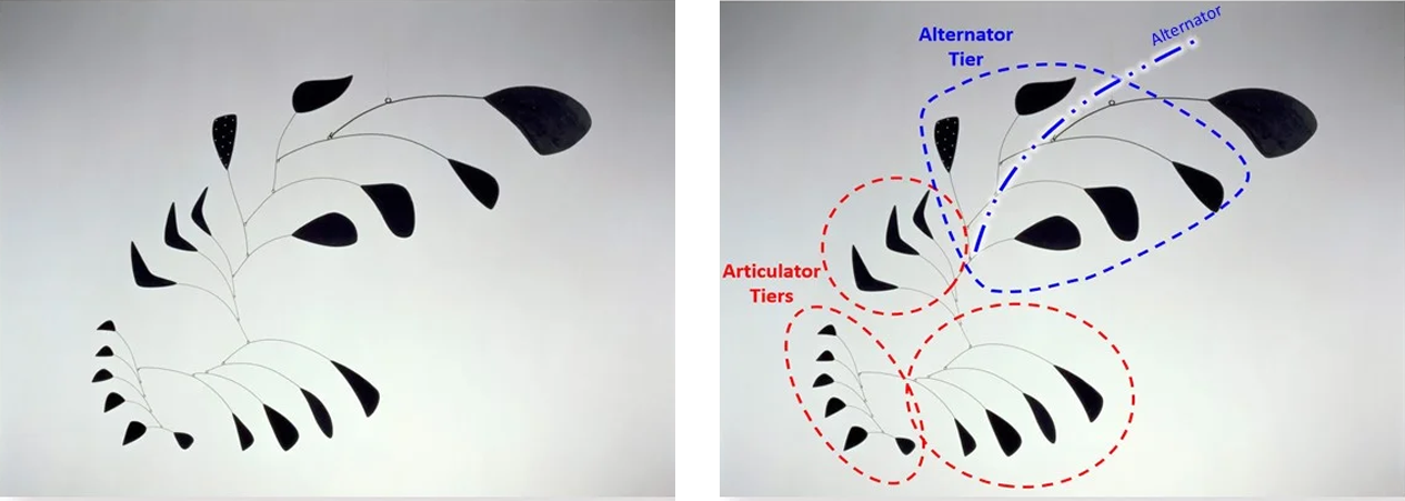
Orientations that follow a fractal, or Fibonacci – like sequence, where each branch-arm that is added progressively moves the center-of-gravity of the tier – is called an Articulator. Its movements remind one of a tail wagging back and forth. It undulates in the wind with a smooth, serpentine fashion.
Conversely, if the arrangement orients the arms around a centerline, then the tier is known as an Alternator. The Cg of this style is more or less fixed – but is subject to the centerline inclination (if it is not vertical). These tiers tend to gyrate around the central connection point.
Many of my current efforts include mirrors that are angled – meaning they are tilted to get the best of both orientations. Angled optics will catch mid-day sun and direct it horizontally. They will capture low angle rays and reflect them vertically. Ideally, the best design incorporates a combination of angled, horizontal as well as vertical optics which blend all aspects of daily solar illumination and there is no competitive interplay between these tiers. The desire is that the mobiles’ mechanical movements – steering the optics along with their following of reflections – are akin to bird murmurations or schools of fish, all in choreographed fluidic motion.
Installation
Proper hanging of an Inflection Point Mobile is dependent on many things. The old adage, “Location, location, location” comes to mind – but then there are many other considerations, like lighting, seasonal adjustments and environments to factor in as well.
Proper hanging of an Inflection Point Mobile involves several parameters beyond just the physical position and mounting hardware. Key factors include adequate lighting, potential for seasonal adjustments, and the specific environmental conditions of the display area.
Viewing mobiles in museums and galleries, I’ve often felt a disconnect: access is restricted, and interaction—moving the piece to make it glide—is prohibited. This standard practice of cordoning off kinetic sculptures often feels counter to the artist’s original intent. However, these restrictions are understandable when considering the vulnerability of the artworks. A large, complex work, such as one weighing 85 pounds of steel and aluminum – crafted decades ago, presents significant conservation challenges, especially if the original artist is no longer available for servicing. The necessity of preservation ultimately limits how “mobile” these kinetic pieces can be, a frustration that, in part inspired me to create my own interactive works.
The most important aspect is safety. Art of this nature is intended for mature audiences and one should always be cautious of those too curious – which can tempt the limits of the materials employed.
Mobiles are storage devices of kinetic energy. The relationship is based on the mass and the height of elevation. The higher the piece and the heavier . . . the more KE potential. Proper anchoring is paramount.
Common engineering practice is to include Safety Factors when designing. If an art piece weighed say 2 pounds – one would like the suspension of that mobile to be capable of handling a lot more. A safety factor of 10 would then indicate any anchor used should be capable of at least 20 pounds. It is common to have multiple safety factors involved in suspension load estimates. My support designs are capable of much more than any environmental impact can deliver. Generally, you’d like your work to survive – even if the building collapses. If your mobile is to hang outdoors, where do you live? What are the temperature extremes? Will it need to withstand high winds? What about rain? Personally, I enjoy the outdoor displays the best. There is something special about seeing all the reflected lights dance through the garden. I continually adjust, move and modulate where our pieces reside around our home. The glass and the coatings on them tend to survive the outdoor elements quite nicely. The metals age with time – some developing a nice patina, others just lightly oxidizing. High-salt, coastal conditions will speed any of these processes along. However, when weather threatens, I will often lower them, bring them inside or store them against a wall to wait for calmer days. You must not ignore these guidelines if you are to hang your mobile outside.
As the mobile moves – it encounters a limit. This ‘hard stop’, will wear gently if the piece is softly moving. If placed in stronger breezes, these ‘stops’ – which are the metal hooks loops – will see more fatigue. The limits of endurance of a piece of metal can eventually be taxed with repeated flexing beyond an elastic limit. Another consideration is wear. Outdoor mobiles are constantly moving where, by comparison, an in indoor piece is rather sedentary.
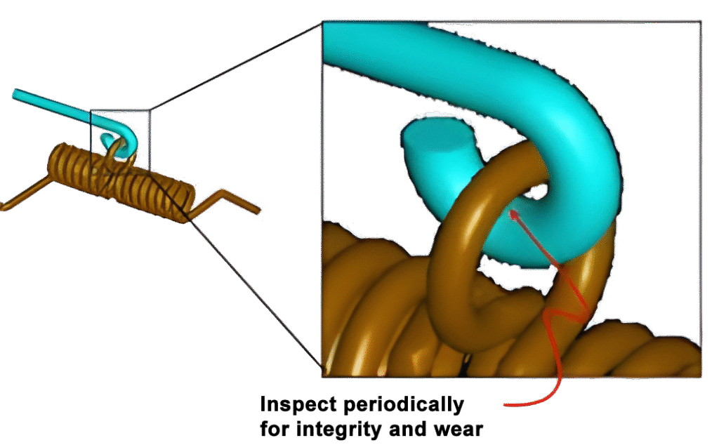
The hook and loop interface on outdoor works will eventually appear worn like an old coin. If placed in a high wind environment and buffeted on a continual basis, a periodic inspection is advised. When installing a mobile outdoors, one needs to always be aware of these maintenance constraints. You want them to move, but ultimately this movement limits their lifetime.
Hanging IPM pieces indoors provides a more controlled environment, avoiding exposure to outdoor elements. The aging of the bronze and copper metals is greatly reduced. Unfortunately, natural sunlight is extremely limited in interior settings. Vaulted ceilings, atriums, staircases or skylights are prime locations for indoor mobiles. Illumination can take the form of spotlights or floodlights positioned to accentuate a room’s décor.
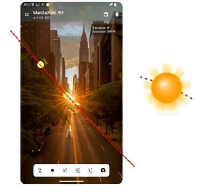
The sun is still the ideal illumination source and this can be tricky in an indoor setting. I used an application called “Sun Position”. It allows me to scan the intended location with my phone camera and it super-imposes the trajectory of the sun throughout the day into the image. The app can also show seasonal adjustments of the solar path. This is quite valuable when evaluating the ideal setting in a room.
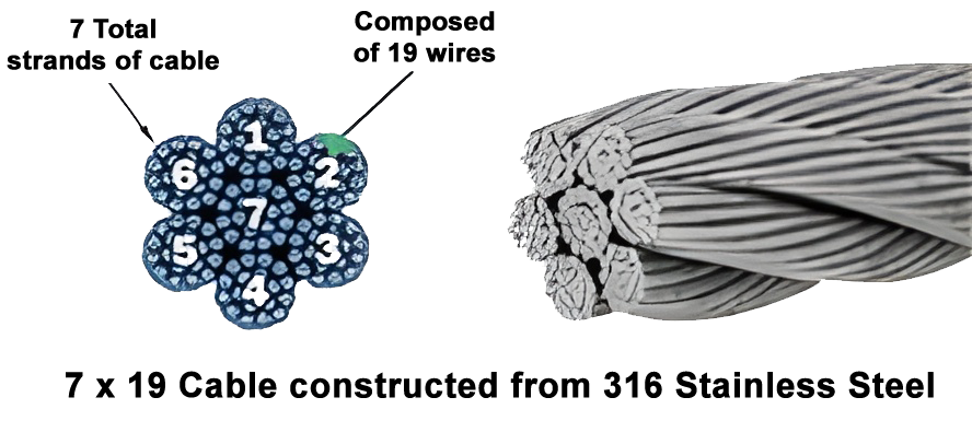
For outdoor settings I typically use and provide a short length of 2mm 316 stainless steel marine cable. Its 7 x 19 construction has superb flexibility and has a break strength of 450 pounds. Accounting for a safety factor of 10, this Maximum BS leads to a maximum WLL load of 45 lbs.
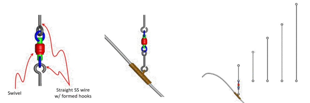
For most indoor schemes I’ve come to prefer straight SS hard-temper wire that is formed with hooks at both ends. Most mobiles employ a swivel to facilitate rotation. The custom formed straight wires are provided in multiple lengths to allow easy adjustment of the height of the piece for maximum sun exposure.
The IPM recommendation is to hang your piece deliberately – planning its intended location with knowledge of the sun to best showcase the reflective nature of the optics. Please contact IPM if you have questions regarding optimal display or installation specifics.
Standing Mobiles
Mobiles fall into a category of art that is known as “site specific”. This means that they are set up in a particular spot with a volume around them for movement. The location cannot be easily transported to the other side of the room (like a painting) without logistical staging to ensure clearance, lighting and other considerations are accounted for. The most important of course is designating the critical anchor point for suspension in the ceiling. Residential settings are particularly daunting to determine the optimal hang location on the first try.
An option to address this dilemma is to make the mobile portable – craft a design where the piece is self-supporting and requires no bolts into a pristine white ceiling. These constructions are known as “standing mobiles”. This type of work, that moves and has branch arms and tiers is distinguished from non-moving, abstract pieces that are called “stabiles”. Calder built many monumental stabiles that are static displays of structural steel forming swooping shapes and arches. He also crafted many kinetic, standing mobiles that spin and gyrate as his hanging works do – but they have the added advantage of portability. The piece can be moved to any desired spot for optimal viewing with no need to re-drill holes or attachment points. This self-contained stature is especially advantageous for reflective kinetic works that enjoy maximum exposure to illumination.
I crafted my first standing mobile in 2010 and quickly realized the opportunity that this style of mobile offered. A table-top sized piece would be an ideal volume to design towards as it provides the ability to track the sun through seasonal changes.
There are subtle but important constraints around standing systems that differentiate them from suspended styles. The most important is establishing a low center-of-gravity point or Cg in the system – upon which everything else is balanced.
Standing Mobile Kinetics and Mass
This is a standing, kinetic-art toy we enjoyed growing up. It is a welded metal figure, on two pointy legs, holding a balance beam, standing on a wooden post.
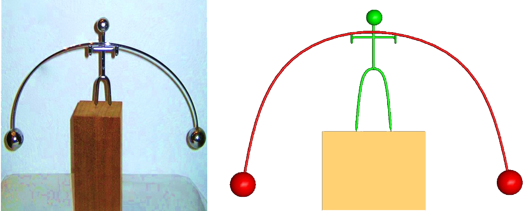
It will tip side to side – balancing on one leg – as it teeters. It will also rock on both legs simultaneously – in and out of the plane of the photograph. Key to this mechanical system are the two spheres at either end of the arc’d balance beam. They are positioned below the ends of the feet of the stickman.
The static condition is below on the left, balanced on the two, pointed legs. The center depicts the tilting mode where stickman balances first on his left leg and then tilts over to the right side. The right illustration shows a rocking mode where stickman leans forward and back – balanced on both points.
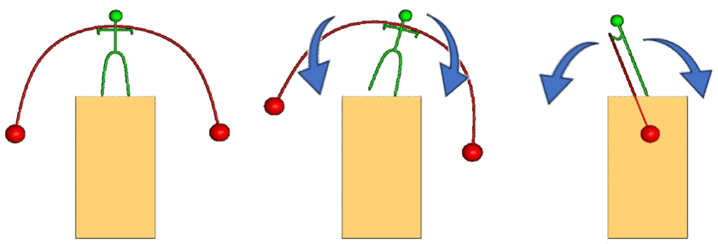
IPM designs typically utilize a single balance point – instead of the two pointy legs. While the above style can rotate, it needs to tip and spin at the same time. Think of the Wizard of Oz’s Tin Man trying to spin around. He can do it if he teeters first on one leg and then the next. IPM efforts typically employ a single balance point.
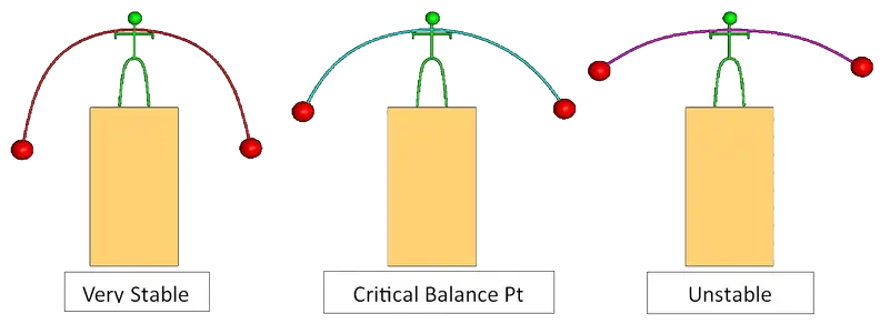
If the curve of balance beam arc is softened, it will raise the spheres to the point – where they are at the same height as the pivot point(s) – which are the ends of stickmans’ legs – and this will destabilize the system – making it want to invert, which causes it to fall. If the arc is increased it will lower the spheres (and essentially the Cg) and the system becomes much more stable.
Most standing mobile designs have “balance beam” arms that are not symetrical – meaning that the mass of one sphere could be larger that the other – allowing one mass to become the “lower mass” and the corresonding upper side could embrace the tier design.
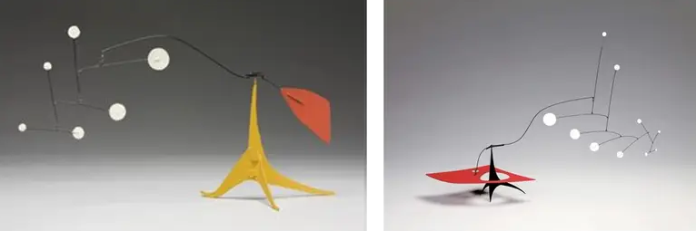
My interpretation of Calders’ evolution into standing mobiles is that he understood the necessity of establishing a low Cg and building off of that initial foundation for extension tiers and appendages. Often, he would make the low mass a large horizontal plate with an aperture to feed the main support through – which is a clever technique for keeping the footprint of the piece small.
Pivots
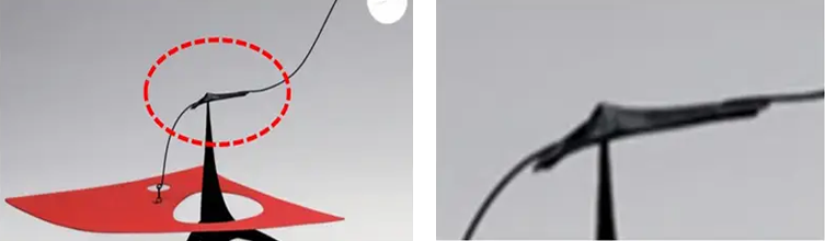
Embracing the challenge of crafting a standing mobile, I was struck by the pivot around which everything would rotate. Calders’ typical method was to take a slender strip of metal and use a forging method to impart a dimple in the center of this shape. This piece would then be inverted (with the impression going up, like a mountaintop) and extension arms would be attached. The entire assembly would then be placed on a pointed rod to complete the pivot scheme.
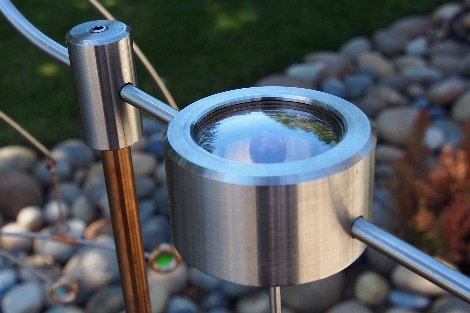
Wanting to improve on this method, I sought to employ a bearing fashioned after a watch pivot. These are typically fabricated from ruby or sapphire as these materials are close to diamond in hardness. I found scrap ruby balls on the open market and paired these shaft-mounted spheres with a double-domed sapphire watch crystal.
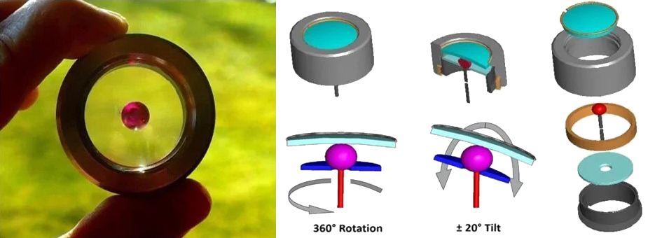
This scheme is used in most of my pieces. The RS Pivot is a sophisticated bearing that spins effortlessly and has the capability to tilt ± 20°.
Here you can see the subtle curvature of the double-domed sapphire utilized in the pivot.
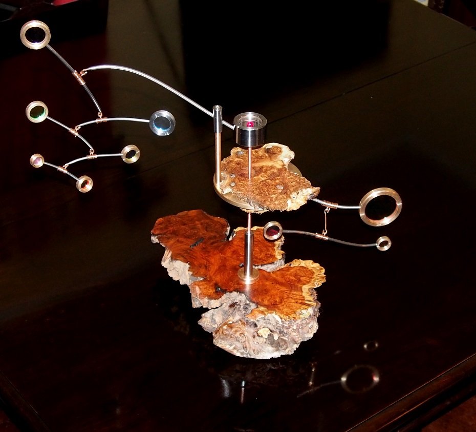
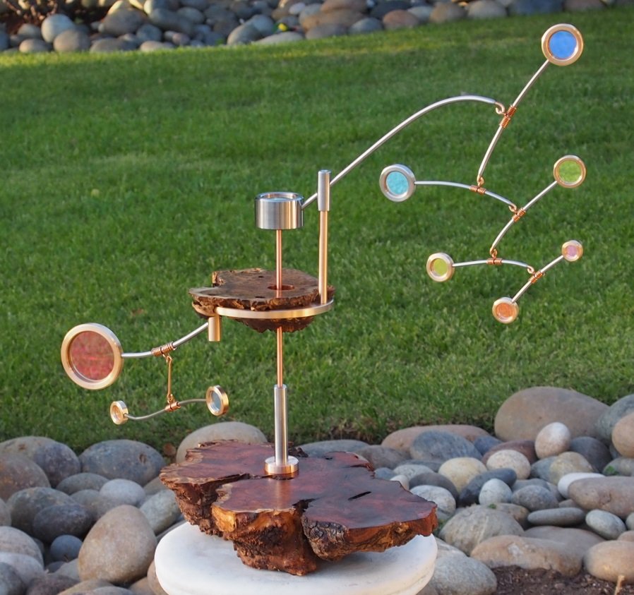
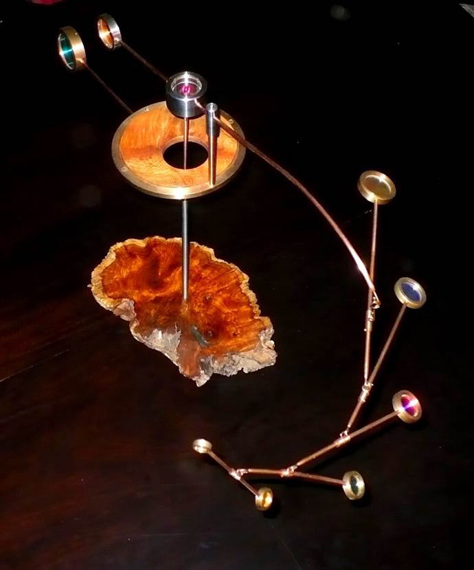
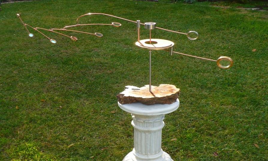
IPM Standing Mobiles
My designs incorporate wood as the base material and can also include a floating island made from a live-edge burls which have extraordinary grain patterns. These wooden elements help soften some of the harshness of all the metal and glass, balancing the aesthetic appeal.
Standing mobiles are the most challenging to make. They require constant attention to mechanics and materials to achieve a design that flows, balances easily, spins with the slightest breeze – and is both compact and portable.